DIY reactive lighting with Arduino, WS2812B Ledstrips and Prismatik
By Aldert Vaandering
June 17, 2015

This relatively easy and cheap DIY project will spruce up your monitor with reactive lighting based on what is displayed on your screen.
It took me about 20 dollars and a few hours of messing around to create it. As usual most of the heavy lifting has been done by others already.
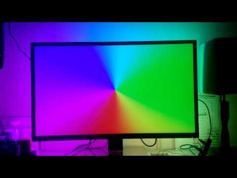
See a working example:
Requirements
- Soldering Iron
- Arduino (any type)
- RGB Led strip supported by FastLED
- Some wires
- Slight programming knowledge to alter the arduino sketch and install the FastLED library
- A 5V power adapter that has enough juice for the amount of LEDs you want to drive. I personally use a 10Amp adapter, driving 110 LEDs. The rule of thumb is 50mA per LED at full brightness, meaning you'll want an adapter that has (0.05 * LED amount) of amps
Let's get started
Step 1. Putting it all together
You want to cut the strips to size, making sure they surround the edge of your monitor, preferably equal lengths on top/bottom and left/right.
Then you'll want to solder the strips together using short lengths of wires, as seen in this image

Once you have everything soldered up you'll want to connect it to your 5V DC adapter and your arduino. Your circuit diagram looks like this:
 Note how the LED strip data line is connected to D2. This could be any of the data pins, as long as you correctly specify it in the next step.
The DC- has to be connected to both the LED strip and the Arduino to properly complete the circuit. It won't work otherwise - some LEDs might light up, but they won't react to any data input.
Step 2. Programming the Arduino
Prepare your arduino.
-
If you haven't installed the Arduino IDE yet, do so by downloading it from here. Once you have it installed, you'll want to download the FastLED library from here and put it in your
{Arduino installation directory}/libraries. -
Open up Arduino and connect to your arduino by selecting the right port through
Tools -> Port.
Now it's time to program your arduino to control the LEDs.
- Copy and paste the following code into your Sketch, making sure you replace the values I highlighted with brackets {{ LIKE THIS }} (sidenote: remove the brackets):
/* LEDstream_FastLED
 *
 * Modified version of Adalight that uses the FastLED
 * library (http://fastled.io) for driving led strips.
 *
 * http://github.com/dmadison/Adalight-FastLED
 *
 * --------------------------------------------------------------------
 * This program is free software: you can redistribute it and/or modify
 * it under the terms of the GNU Lesser General Public License as published by
 * the Free Software Foundation, either version 3 of the License, or
 * (at your option) any later version.
 *
 * This program is distributed in the hope that it will be useful,
 * but WITHOUT ANY WARRANTY; without even the implied warranty of
 * MERCHANTABILITY or FITNESS FOR A PARTICULAR PURPOSE.  See the
 * GNU Lesser General Public License for more details.
 *
 * You should have received a copy of the GNU Lesser General Public License
 * along with this program.  If not, see <http://www.gnu.org/licenses/>.
 * --------------------------------------------------------------------
 */

// --- General Settings
static const uint16_t
  Num_Leds   =  {{ YOUR NUMBER OF LEDS HERE }};        // strip length
static const uint8_t
  Led_Pin    =  {{ YOUR DATA PIN HERE }},         // Arduino data output pin
  Brightness =  255;       // maximum brightness

// --- FastLED Setings
#define LED_TYPE     {{ WS2812B <-- REPLACE THIS WITH YOUR LED STRIP CHIPSET }} //   // led strip type for FastLED
#define COLOR_ORDER  {{ GRB <-- REPLACE THIS WITH YOUR COLOR ORDER }}     // color order for bitbang

// --- Serial Settings
static const unsigned long
  SerialSpeed    = 2000000; // serial port speed
static const uint16_t
  SerialTimeout  = 0;     // time before LEDs are shut off if no data (in seconds), 0 to disable

// --- Optional Settings (uncomment to add)
#define SERIAL_FLUSH         // Serial buffer cleared on LED latch
//#define CLEAR_ON_START     // LEDs are cleared on reset
//#define GROUND_PIN 10      // additional grounding pin (optional)
//#define CALIBRATE          // sets all LEDs to the color of the first

// --- Debug Settings (uncomment to add)
//#define DEBUG_LED 13       // toggles the Arduino's built-in LED on header match
//#define DEBUG_FPS 8        // enables a pulse on LED latch

// --------------------------------------------------------------------

#include <FastLED.h>

CRGB leds[Num_Leds];
uint8_t * ledsRaw = (uint8_t *)leds;

// A 'magic word' (along with LED count & checksum) precedes each block
// of LED data; this assists the microcontroller in syncing up with the
// host-side software and properly issuing the latch (host I/O is
// likely buffered, making usleep() unreliable for latch). You may see
// an initial glitchy frame or two until the two come into alignment.
// The magic word can be whatever sequence you like, but each character
// should be unique, and frequent pixel values like 0 and 255 are
// avoided -- fewer false positives. The host software will need to
// generate a compatible header: immediately following the magic word
// are three bytes: a 16-bit count of the number of LEDs (high byte
// first) followed by a simple checksum value (high byte XOR low byte
// XOR 0x55). LED data follows, 3 bytes per LED, in order R, G, B,
// where 0 = off and 255 = max brightness.

static const uint8_t magic[] = {
  'A','d','a'};
#define MAGICSIZE  sizeof(magic)

// Check values are header byte # - 1, as they are indexed from 0
#define HICHECK    (MAGICSIZE)
#define LOCHECK    (MAGICSIZE + 1)
#define CHECKSUM   (MAGICSIZE + 2)

enum processModes_t {Header, Data} mode = Header;

static int16_t
  c;
static uint16_t
  outPos;
static uint32_t
  bytesRemaining;
static unsigned long
  t,
  lastByteTime,
  lastAckTime;

// Debug macros initialized
#ifdef DEBUG_LED
  #define ON  1
  #define OFF 0

  #define D_LED(x) do {digitalWrite(DEBUG_LED, x);} while(0)
#else
  #define D_LED(x)
#endif

#ifdef DEBUG_FPS
  #define D_FPS do {digitalWrite(DEBUG_FPS, HIGH); digitalWrite(DEBUG_FPS, LOW);} while (0)
#else
  #define D_FPS
#endif

void setup(){
  #ifdef GROUND_PIN
    pinMode(GROUND_PIN, OUTPUT);
    digitalWrite(GROUND_PIN, LOW);
  #endif

  #ifdef DEBUG_LED
    pinMode(DEBUG_LED, OUTPUT);
    digitalWrite(DEBUG_LED, LOW);
  #endif

  #ifdef DEBUG_FPS
    pinMode(DEBUG_FPS, OUTPUT);
  #endif

  FastLED.addLeds<LED_TYPE, Led_Pin, COLOR_ORDER>(leds, Num_Leds);
  FastLED.setBrightness(Brightness);

  #ifdef CLEAR_ON_START
    FastLED.show();
  #endif

  Serial.begin(SerialSpeed);
  Serial.print("Ada\n"); // Send ACK string to host

  lastByteTime = lastAckTime = millis(); // Set initial counters
}

void loop(){
  adalight();
}

void adalight(){
  t = millis(); // Save current time

  // If there is new serial data
  if((c = Serial.read()) >= 0){
    lastByteTime = lastAckTime = t; // Reset timeout counters

    switch(mode) {
      case Header:
        headerMode();
        break;
      case Data:
        dataMode();
        break;
    }
  }
  else {
    // No new data
    timeouts();
  }
}

void headerMode(){
  static uint8_t
    headPos,
    hi, lo, chk;

  if(headPos < MAGICSIZE){
    // Check if magic word matches
    if(c == magic[headPos]) {headPos++;}
    else {headPos = 0;}
  }
  else{
    // Magic word matches! Now verify checksum
    switch(headPos){
      case HICHECK:
        hi = c;
        headPos++;
        break;
      case LOCHECK:
        lo = c;
        headPos++;
        break;
      case CHECKSUM:
        chk = c;
        if(chk == (hi ^ lo ^ 0x55)) {
          // Checksum looks valid. Get 16-bit LED count, add 1
          // (# LEDs is always > 0) and multiply by 3 for R,G,B.
          D_LED(ON);
          bytesRemaining = 3L * (256L * (long)hi + (long)lo + 1L);
          outPos = 0;
          memset(leds, 0, Num_Leds * sizeof(struct CRGB));
          mode = Data; // Proceed to latch wait mode
        }
        headPos = 0; // Reset header position regardless of checksum result
        break;
    }
  }
}

void dataMode(){
  // If LED data is not full
  if (outPos < sizeof(leds)){
    dataSet();
  }
  bytesRemaining--;

  if(bytesRemaining == 0) {
    // End of data -- issue latch:
    mode = Header; // Begin next header search
    FastLED.show();
    D_FPS;
    D_LED(OFF);
    #ifdef SERIAL_FLUSH
      serialFlush();
    #endif
  }
}

void dataSet(){
  #ifdef CALIBRATE
    if(outPos < 3)
      ledsRaw[outPos++] = c;
    else{
      ledsRaw[outPos] = ledsRaw[outPos%3]; // Sets RGB data to first LED color
      outPos++;
    }
  #else
    ledsRaw[outPos++] = c; // Issue next byte
  #endif
}

void timeouts(){
  // No data received. If this persists, send an ACK packet
  // to host once every second to alert it to our presence.
  if((t - lastAckTime) >= 1000) {
    Serial.print("Ada\n"); // Send ACK string to host
    lastAckTime = t; // Reset counter

    // If no data received for an extended time, turn off all LEDs.
    if(SerialTimeout != 0 && (t - lastByteTime) >= (uint32_t) SerialTimeout * 1000) {
      memset(leds, 0, Num_Leds * sizeof(struct CRGB)); //filling Led array by zeroes
      FastLED.show();
      mode = Header;
      lastByteTime = t; // Reset counter
    }
  }
}

void serialFlush(){
  while(Serial.available() > 0) {
    byte r = Serial.read();
  }
}
- Click upload!
Step 3. Controlling the LEDs
Now comes the fun part: Letting the lights dance!
-
Download and install the Prismatik release by psieg
-
Open Prismatik and set it up by going to
Device -> Configuration Wizard
All done! Once you have everything set up accordingly, your monitor should be extended by your LED strips. Go play a movie or play a game and check it out!
Amsterdam
The Netherlands
Arusan
KvK 84379057
1-201 taartskceeblaW